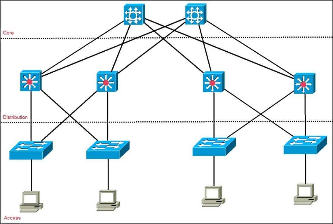
Three-Tier Network Topology – The Classic Enterprise Architecture

6
As networks grew in size and complexity, engineers realized it was impossible to efficiently manage environments where all devices were connected randomly or without structure.
This led to the creation of one of the most important models in enterprise networking:
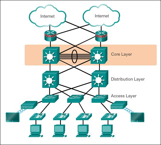
👉 The Three-Tier Network Architecture (Core – Distribution – Access)
This model was developed to:
- organize equipment physically,
- simplify expansion,
- increase redundancy,
- provide high availability,
- separate responsibilities between layers,
- and standardize how networks are built worldwide.
Today, any medium or large company uses this model — and you will encounter it in your daily work as a network analyst.
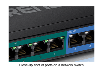
🔹 Access Layer – Where Everything Begins


6
Now that you understand Layer 2 switches, their role becomes clear:
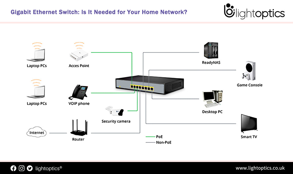
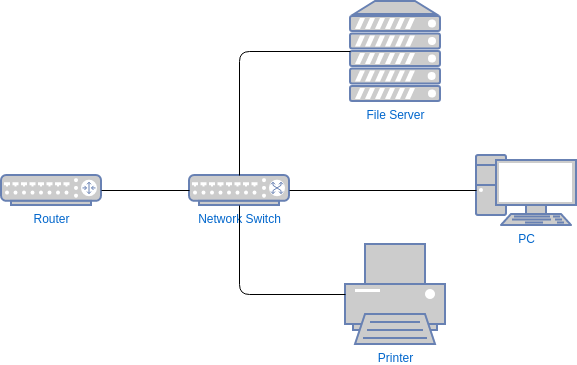
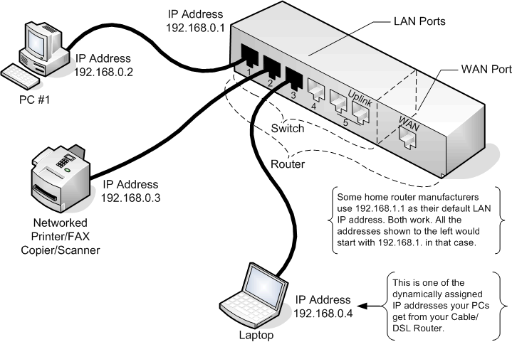
👉 The access layer is where all end-user devices connect.
Here we connect:
- computers
- printers
- IP phones
- cameras
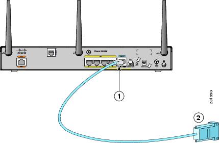
- access points
- IoT devices
- any user-facing equipment
And for this reason:
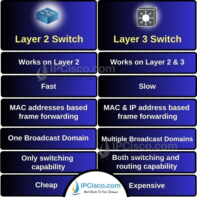
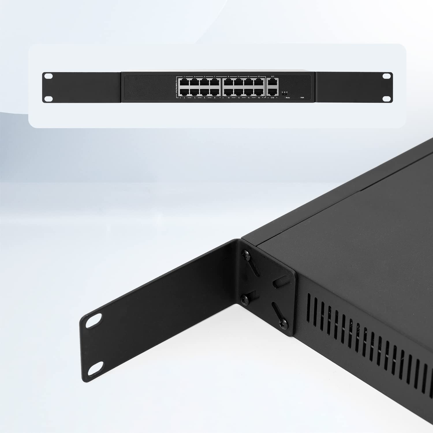
✔ Access switches are almost always Layer 2.
Their job is simply to provide physical connectivity.
❌ Can we use Layer 3 switches in the access layer?
Technically yes — but it is a waste of money.
Layer 3 switches are more expensive, and their routing capabilities should not be used in this layer when following the three-tier model.
They would be underutilized.
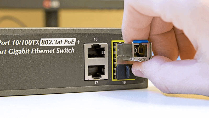
🔹 Distribution Layer – The Internal “Brain” of the Network


6
The distribution layer is responsible for making the internal network communicate with itself.
👉 This is where we start using Layer 3 switches, mainly through SVIs.
Typical responsibilities of the distribution layer include:
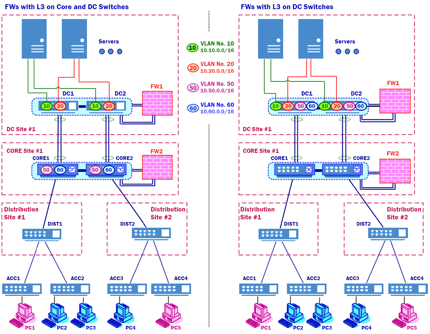
- inter-VLAN routing
- applying internal routing policies
- aggregating multiple access switches
- controlling how traffic flows inside the organization
- redundancy mechanisms (HSRP/VRRP/GLBP)
Think of it as an internal control center:
- it receives traffic from access switches,
- routes it as needed,
- forwards it to the core when appropriate.
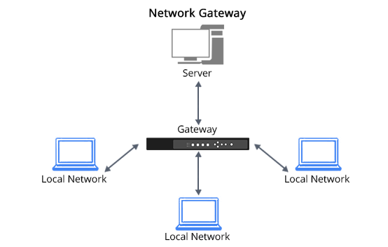
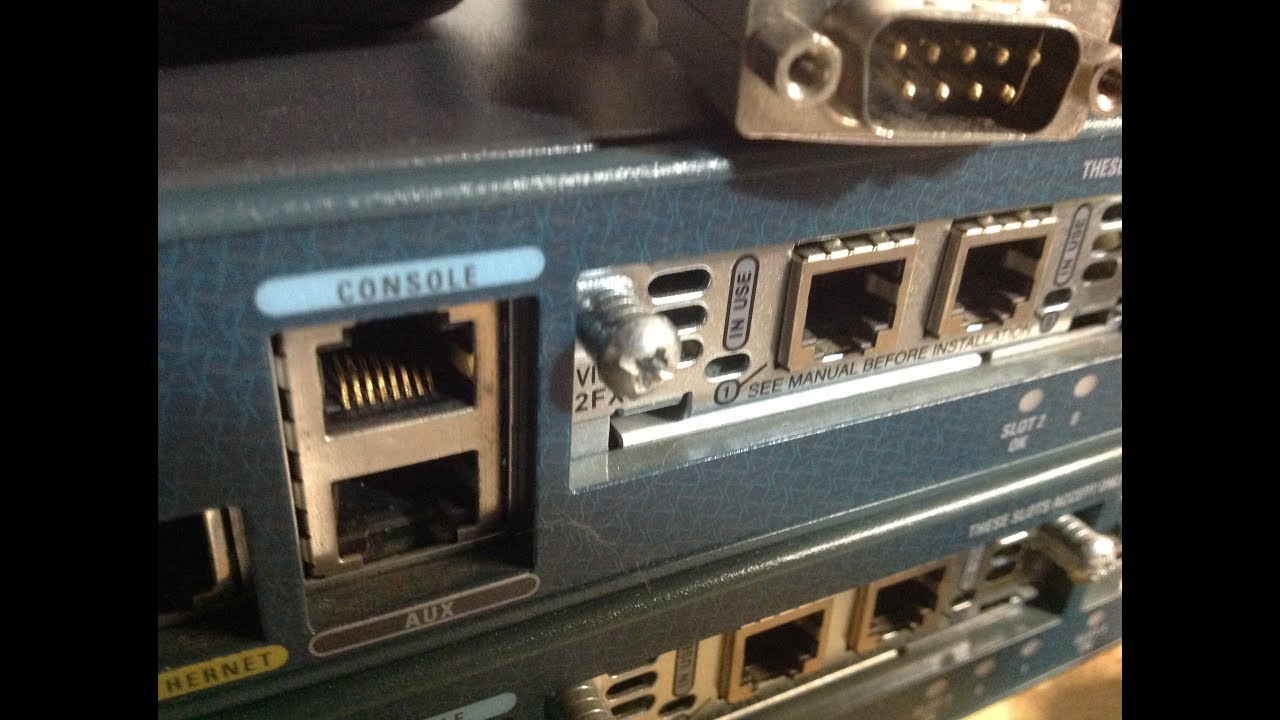
🔹 Core Layer – The Center of the Network (and the Path to the World)
6
The core layer is the most critical part of the internal network.
Its responsibilities include:
- interconnecting all internal networks,
- connecting the company to other branches,
- connecting to the firewall and the ISP router,
- reaching the Internet,
- handling high-speed internal routing.
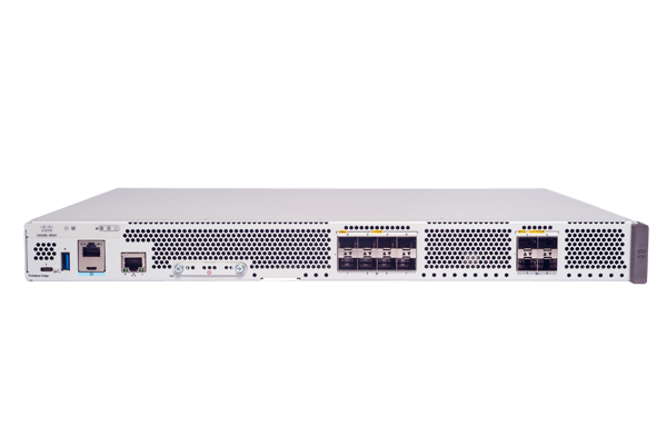
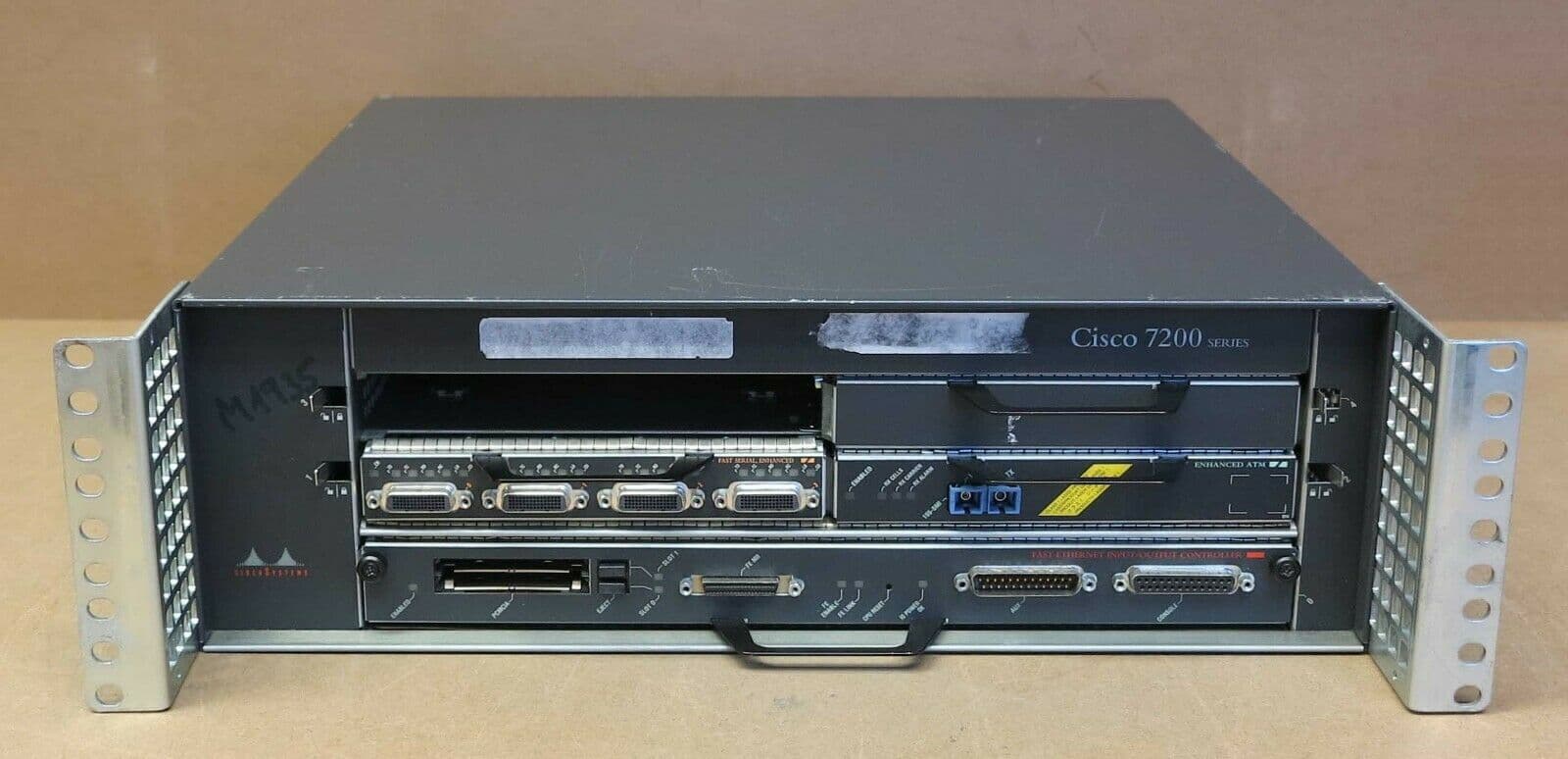
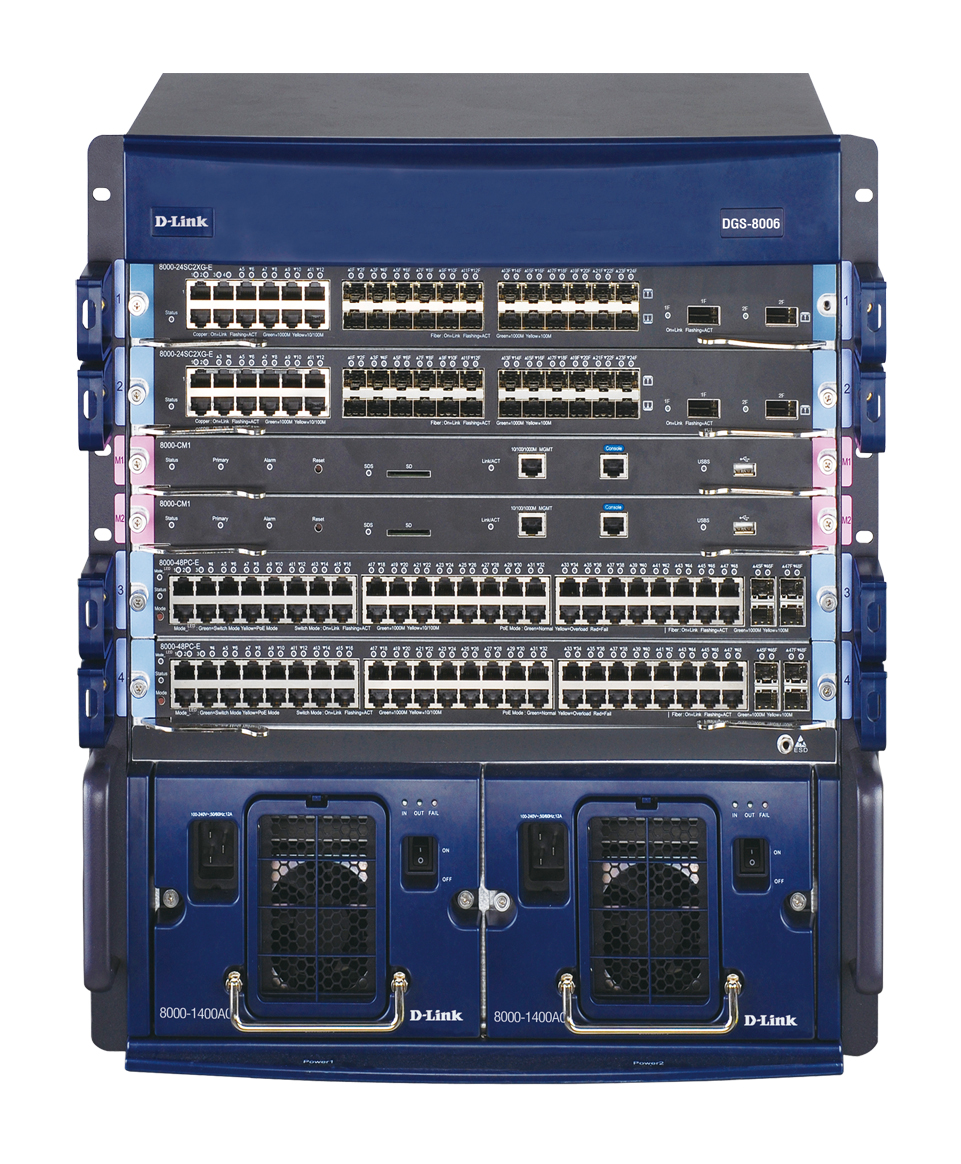
Equipment used in the core:
- very high-performance Layer 3 switches, or
- enterprise-grade routers.
This is the company’s highway — where all major traffic flows.
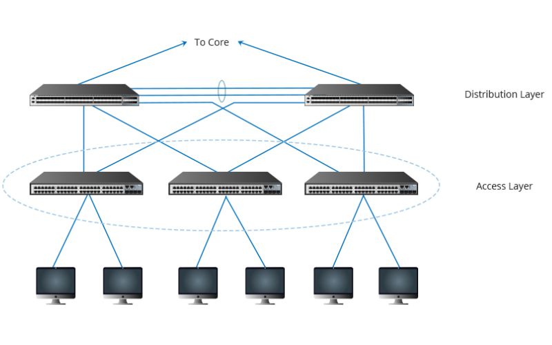
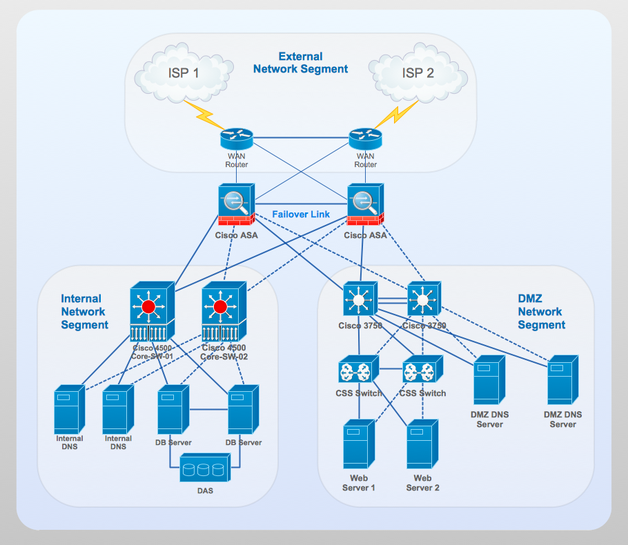
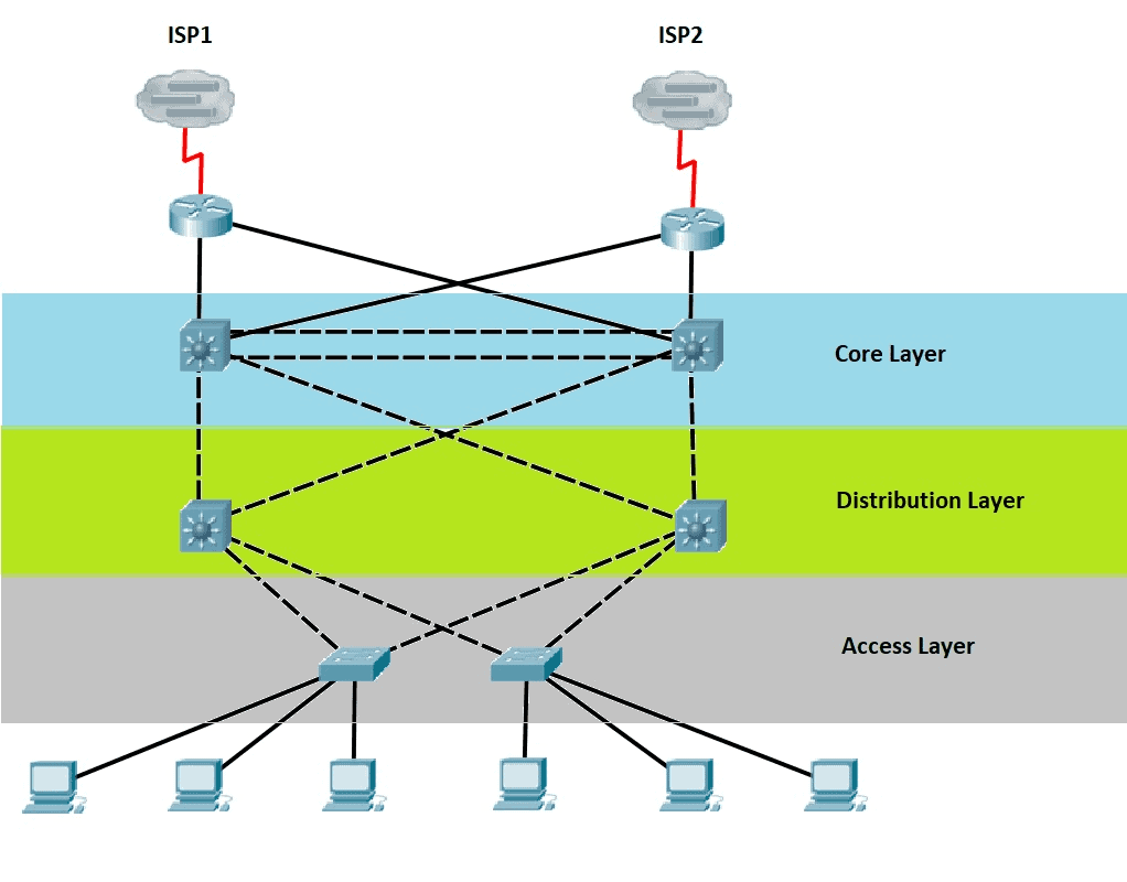
🏛️ Our Demonstration Topology
For the course, we will work with the following environment:
🔹 6 Access Switches (L2)
for user devices.
🔹 2 Distribution Switches (L3)
for inter-VLAN routing and aggregation.
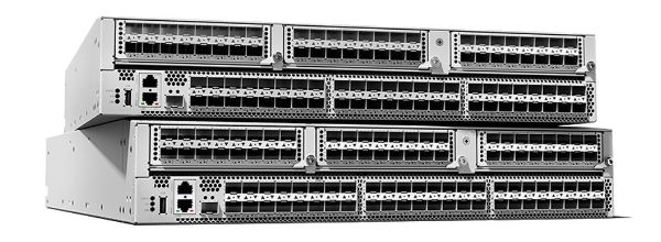
🔹 2 Core Switches (High-performance L3 or routers)
to connect the internal network with the outside world.

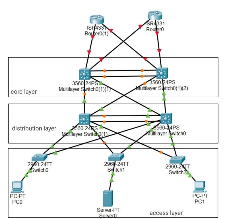

4
This layout is extremely common in real enterprise environments.
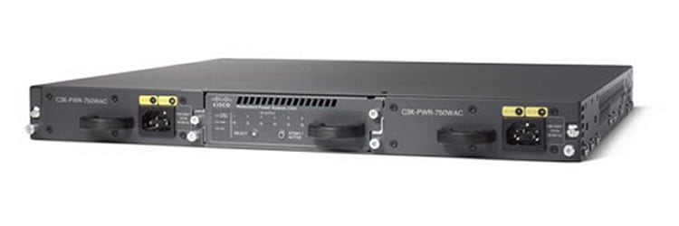
🔄 Why Distribution and Core Must Always Be Redundant
The distribution and core layers don’t just connect devices —
they connect networks.
For this reason:
👉 If one of these layers fails and no backup exists, the entire company can go offline.
Examples:
- If a core switch goes down → the company loses Internet and branch connectivity.
- If a distribution switch goes down → entire floors, VLANs, or departments go offline.
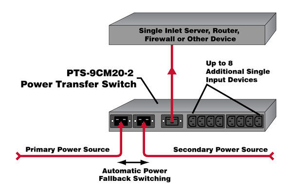
This is why redundancy is mandatory:
- two distribution switches working together,
- two core switches for high availability,
- redundant links everywhere,
- routing failover mechanisms.
Professional networks rarely operate without redundancy.
If they do, serious outages are inevitable.
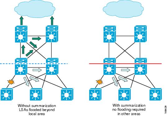
🧩 Physical Topology vs Logical Topology
The three-tier architecture represents the physical structure:
- which device connects where,
- how cabling is organized,
- what role each switch plays.
But there is another equally important perspective:
👉 The Logical Topology
This represents:
- how traffic moves between VLANs,
- how routing decisions occur,
- how redundancy protocols behave,
- how spanning-tree interacts with the topology,
- how primary and backup paths are used.
We will explore the logical topology later in the course.